
The purpose of this document is to describe how files are organized under the Wang 2200 file system. This scheme started with the first generation 2200 family, and was kept with slight enhancements for the VP and MVP series of operating systems. In fact, some of the file organization comes directly from the structure of files on cassette tape, which predated the disk drives.
The first part is a general background on Wang's disk structure. This information is readily available in the disk reference manuals, so only the essentials will be touched upon here. The second part has details that are not in the manuals, and were collected from various other sources, including experimentation.
All Wang disks use 256 byte sectors. The number of sectors per track and the number of tracks vary across different media, but these details are not exposed to Wang BASIC. To BASIC, a disk consists of a linear stream of sectors numbered 0 to (# of sectors on disk - 1). Hard disk controllers take care of bad sector mapping, not the operating system, so that detail too is hidden from BASIC, and so it also not covered here.
Unstructured Disks (link)
Wang BASIC allows a program to read and write an arbitrary sector on the disk, just as simply as this:
10 DIM A$(16)16
20 DATALOAD BA F (0,N) A$()
30 HEXPRINT A$()
This read sector 0 of the fixed disk on the currently selected drive into the 256 byte array, A$(), then prints it out in hex. The "B" of the "BA" part of the command is what says to read the sector as a binary (that is, uninterpreted) and the "A" of "BA" indicates absolute sector addressing.
For some applications, it makes sense to do everything this way. The organization of the data on the disk is completely up to the application. This really only makes sense for storing data, not programs. Such random access sectors is allowed even for disks that are structured, and there is no protection mechanism to prevent a program from clobbering a disk through buggy or malicious code.
Uncataloged Disks (link)
For most people, though, it is much more convenient to use the ability of Wang BASIC to operate on files as coherent entities.
Files are organized as a sequence of sectors that are contiguously allocated on the disk. There are control bytes embedded in the blocks to help interpret the files when they are read back in. The structure of program and data files are somewhat different, which is detailed later.
A user (or program) can manage file allocation itself. By knowing what range of sectors is allocated to a given file, the file can be accessed later using the same absolute sector numbers.
For instance, a user may have a program in memory and wants to save it for later. He can save it, clear memory, and read it back like this:
:SAVE DAF (100)
:CLEAR
:LOAD DAF (100)
The first statement stores the program (with no name) starting at sector 100 of the disk. The program will take as many sectors as required to write out the program. The second statement clears memory. The third statement loads the program back in again.
Similar commands (DATALOAD DA ..., DATASAVE DA ...)
are used for reading and writing data records to disk at an absolute sector
address. Data file structure will be detailed later in this document.
Manually placing files gives the user and applications flexibility in making allocation policy for a disk, but it is also a burden to keep track of where each file begins, how many sectors are allocated to it, and how many of its allocated sectors are in use.
Cataloged Disks (link)
Wang BASIC also had a "catalog" mechanism, which was a simple table to map filenames to locations on the disk.
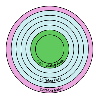
After formatting, a disk is "scratched", meaning the catalog is initialized to an empty state. The user also specifies how much of the disk is to be used to hold the catalog table, how much of the disk should be used for holding the cataloged files, and how much (if any) of the remainder of the disk should be reserved so that applications can count on at least part of the disk being free for the application to use for holding uncataloged files. For instance, an 8" floppy disk has 1024 sectors. This command will initialize the disk to say that 20 sectors should be used to hold the catalog index (the mapping table), 800 sectors for holding the cataloged files, and the remainder (204 sectors) for temp files:
SCRATCH DISK F LS=20,END=819
In the diagram below, the outer track is track 0. The first 20 sectors (the LS=20 part) hold the catalog index, and is colored purple. Sectors 20 through 819 for holding files, and is powder blue. Not all of this area is necessarily in use. The uncommitted sectors, 820 to 1023, are colored green.
The catalog directory is a flat structure, that is, there are no subdirectories. There are no protection mechanisms, so any user can access and modify any sector or file on the disk. Files are allocated statically; that is, a file can only get as large as the space set aside for it when it was created. When a file is deleted (scratched in Wang parlance), the space is not reclaimed automatically.
Index Structure (link)
Here is where things start getting more technical.
The SCRATCH DISK command initializes the disk for use
with the disk catalog (DC) commands. The LS= parameter indicated how
many sectors are to be used for holding the file catalog. Each sector
can hold entries for sixteen files, except the first (sector 0), which
can hold entries for fifteen files.
Each sector is subdivided into sixteen blocks, each sixteen bytes long. Each entry holds the mapping of a filename to its status and location on the disk. The first entry of the first sector is treated specially and does not hold file mapping information; it will be described next. As a result, if N sectors are reserved for the index, a disk can hold up to (16*N-1) files. Because of the way things are arranged, this limit includes both active and deleted files.
Disk Parameter Block (link)
The first sixteen bytes of sector zero are set aside to hold the disk parameter block. This holds the information specified by the SCRATCH DISK command.
| Byte offset | Meaning |
|---|---|
| 0 | Index style
|
| 1 | Number of catalog index sectors |
| 2,3 | MS,LS bytes of number of sectors reserved for holding cataloged files |
| 4,5 | MS,LS byte of next sector to be allocated for a cataloged file |
| 6 ... 15 | unused |
The first byte indicates what style of catalog the disk uses. For the moment let's ignore this distinction, as it is minor. The next byte holds how many sectors are set aside to hold the file index.
Bytes 2 and 3 are a 16b value indicating how many sectors immediately after the catalog index sectors should be set aside for holding files.
Bytes 4 and 5 are a 16b value pointing to the first unallocated sector. When a new file is created, this will be the location of its first sector, and then this field will be incremented by the number of bytes allocated for the new file.
In both new and old style indexes, two byte sector addressing is used, which implies that a disk can have at most 64K sectors (about 8 MB) on a platter. This probably seemed spacious in 1971, but it quickly became limiting. Wang attempted to work around it by making large disks appear to be partitioned as a number of smaller disks, but eventually they were forced to allow a larger sector address. This was called tri-byte addressing by Wang.
| Byte offset | Meaning |
|---|---|
| 0 | Index style
|
| 1,2 | MS,LS number of catalog index sectors |
| 3,4,5 | MS to LS bytes of number of sectors reserved for holding cataloged files |
| 6,7,8 | MS to LS byte of last sector allocated to a cataloged file |
| 9 ... 15 | unused |
The fields mean the same thing as before, except now more files and larger files are allowed. Having three bytes of sector address means that this mode handles disks up to 4 GB. Despite allowing the huge size, the catalog structure was still a flat file system.
Disk Catalog Index Entries (link)
Each sector of the index holds sixteen entries (except the first, which has only fifteen). The arrangement of each entry is described below:
| Byte offset | Meaning |
|---|---|
| 0 | File Status
In practice, only these combinations are seen:
|
| 1 | File Type
|
| 2,3 | MS,LS bytes of location of first sector allocated for file |
| 4,5 | MS,LS bytes of location of last sector allocated for file |
| 6,7 | unused |
| 8 .. 15 | File name; end padded with spaces if fewer than eight characters |
| Byte offset | Meaning |
|---|---|
| 0 | File Status; same as for 16-bit addressing |
| 1 | File Type; same as for 16-bit addressing |
| 2,3,4 | MS to LS bytes of location of first sector allocated for file |
| 5,6,7 | MS to LS bytes of location of last sector allocated for file |
| 8 .. 15 | File name; same as for 16-bit addressing |
When a disk is scratched, all entries are set to 0x00. This means that the first byte will be 0x00, unused. If an entry is unused, all other fields of the entry are meaningless. When a file is created, either program or data file, the status byte is set to 0x10, meaning "valid entry", and all the other fields are meaningful. If the disk is scratched (marked for removal), the byte is set to 0x11. In this state, the other fields are still meaningful, and the space allocated for the file originally still holds its original contents.
Scratching a file is more like a reminder that the file is no longer desired, and attempts to open such a file produce an error. Scratched files can be reused, for instance if a later revision of a program can be written over the previous revision. It is also possible to write a file with a different name over a scratched entry; the new filename may hash to a different location in the index, so the old entry is set to 0x21 to indicate that the entry is not valid and can't be recycled again. The entry isn't set to 0x00 since there may other entries in the index sector, and a 0x00 entry would confuse the index bookkeeping. The reason for this is described in the next section.
Note that the index contains information about the space on disk allocated to the file, but it doesn't know how much of the allocated space is actually used. This information is kept with the file.
Locating a File (link)
When a Wang BASIC program creates a file or opens an existing file, an eight byte filename is presented. Depending on the index style, one of two hashing algorithms is applied to the filename to produce a number between 0 and (number_of_index_sectors - 1). This sector is read off the disk and all 15 or 16 entries are searched, from first to last, for an entry with a filename that matches. If a match is found, then that entry supplies the location and size of the file, and all is well.
If an unused entry is found (0x00 status byte), that entry will be used to place the file for a newly created file, or if we are attempting to find an existing file, it means the file is not on the disk, and an error will be generated.
If all entries in the sector have been searched unsuccessfully and no unused entries are found, it means that hash bucket is full, and another sector is searched for the overflow. In the case of disks with the old style index, the previous sector is searched, and if that is inconclusive, the one previous to that is searched, modulo the number of index sectors, etc., until all index sectors have been searched. In the case of the new style and tri-byte addressing, on a bucket overflow the search is continued in the forward direction instead.
The hash algorithm for old style indexes is as follows:
    pad the end of the filename with spaces until it is eight bytes
    tmp = 0x00
    foreach character in filename
        tmp ^= character
    tmp = 3*tmp
    tmp = (tmp mod 256) + int(tmp/256)  // fold over carries
    hash = tmp mod (number of index sectors)
That hash algorithm, for certain sizes of index tables, produced a poor hash, meaning only 1/3 of the entries were ever used, resulting in a lot of hash bucket overflows and slow search times. Starting in MVP OS 2.5, the new hash algorithm was introduced. At the time a disk was scratched, the user specified whether the old or new index style should be used.
The hash algorithm for new style indexes is as follows:
    pad the end of the filename with spaces until it is eight bytes
    tmp = 0x00
    foreach character in filename
        if 1st, 3rd, 5th, or 7th character:
            tmp += 16*(tmp mod 16) + int(tmp/16)  // swap nibbles
        else
            tmp += character
    tmp = tmp mod 256
    hash = tmp mod (number of index sectors)
I am uncertain what hash algorithm was used for the tri-byte disk indexes. This format allows up to 64K sectors to be used for the index, yet the previous algorithms only produce a hash that might range from 0 to 255.
Program File Structure (link)
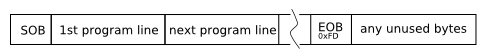
Program files contain more information than just the program listing. The following diagram shows the overall view of a program file. Note that the space allocated to the file might be more than the program needs, in which case there may be unused blocks after the program.
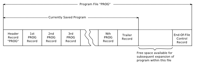
Each of these blocks will be described next.
SOB Control Byte
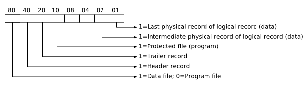
Each sector begins with a control byte, called the SOB byte, for Start of Block. The control byte contains information about what is contained in a block. Only certain sequences of blocks are allowed, and so it also helps ensure file integrity as it is a means of checking for a valid file structure.
At first blush it might seem like there is more information there than is absolutely required. But keep in mind that files, especially data files, need to be searchable both forwards and backwards, as Wang BASIC has commands to advance the file pointer by logical records as well as by blocks. This was especially true for earlier machines that used tape drives instead of disks, but it still makes things simpler for disk-based searches too.
In the diagram below, one of the bits is used only by program files, and are marked with "(program)". Some of the bits are used only by data files, and those are marked "(data)". Only certain combinations of flags are seen in practice, which are called out later.
Header Record
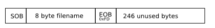
The first sector of a program file is a header record. The header record has this structure:
| Offset | Meaning |
|---|---|
| 0 | SOB Control Byte:
|
| 1 to 8 | Filename, padded with spaces at the end |
| 9 | 0xFD = End Of Block (EOB) |
| 10 to 255 | unused |
Program Records
After the header block, there are the sectors containing the program. The program is saved in tokenized format, and the tokens are consistent in all versions of Wang BASIC and Wang BASIC-2. Lines are never split across a sector. An EOB (0xFD) byte is placed after the last line that will fit in the sector. In the final sector, an EOD (0xFE), End of Data, byte is used instead of the EOB byte.
The layout is given in the following table:
| Byte | Meaning |
|---|---|
| 0 | SOB Control Byte
|
| 1 to N | N bytes of tokenized program lines |
| N+1 | 0xFD: End of Block byte |
| N+2 to 255 | unused |
Trailer Record
The last record is identical in layout to the intermediate records, except that the control byte is different to flag that it is the last block, and the terminating byte after the program lines is also different. If a program is short enough to fit into a single record, then the trailer record will immediately follow the header record.
| Byte | Meaning |
|---|---|
| 0 | SOB Control Byte
|
| 1 to N | N bytes of tokenized program lines |
| N+1 | 0xFE: End of Data byte |
| N+2 to 255 | unused |
Unused Records
After the trailer record, there may be a number of unused sectors if the file was allocated to be larger than required. These unused blocks are ignored when the file is read in, as you might expect.
Control Record
In the last sector of the space allocated for the file is a control record. Byte 0 of the sector contains 0x20 (for program files). The next two bytes contain a count of the number of sectors actually used by the file, including the header record and the trailer record. The most significant byte is stored first. Because of the presence of the header and control record blocks, a minimum sized file will always require at least three sectors on the disk.
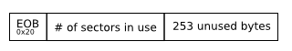
The SOB control byte will always be 0x20, even if the file was written with protection enabled.
Data File Structure (link)
The structure of data files has some elements in common with the way program files are structured, but many things are also different.
Like program files, a fixed number of sectors is allocated for data files at the time the file is first created. Like program files, there is a control block stored in the last sector of the allocated space recording how many of the allocated sectors are actually in use (including the control record). Like program files, each sector of a data file contains a control byte that indicates the structural purpose of the sector.
Unlike program files, data files have two control bytes, not just one. Unlike program files, data files don't have a header record (this is somewhat surprising since program files do, and also since data files on cassette tape have a header record).
As was just stated, sectors containing data have two control bytes. The first control byte is similar to that of the program files, and indicates if the sector is the non-terminal sector of a multi-sector logical record (0x82), or if it is the last sector of a logical record (0x81), or if the data stream has ended (0xA0).
The second byte is the sector number of the logical record. It starts counting at 0x01 and increments by one for each subsequent sector of the logical record. Because a logical record is whatever is contained in the variable list of the DATASAVE command, a record will always have fewer than 64K bytes of data, thus it will always fit in fewer than 256 sectors.
A logical record that is small enough that it fits within one sector will have control bytes of 0x82 0x01.
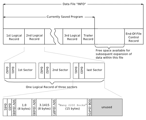
The next diagram shows the layout of a file, a logical record within a file, and a sector of a logical record. For the sake of example, the second logical record is assumed to occupy three sectors on the disk. The first sector begins with the control bytes 0x82 0x01. Looking back at the diagram of the control byte, we see that the 0x80 part means it is a data sector, and the 0x02 part means this sector isn't the last of the logical record. The sequence byte is 0x01 as this is the first sector. The next sector has 0x82 0x02, meaning non-terminal data sector, second sector of logical record. The third sector starts with 0x81 0x03, meaning last sector of the logical data record, third sector.
Looking inside that third sector, we see the more detailed structure of the data. Again, it starts with the control byte of 0x81, and the sequence number of 0x03. After that, data records consist of pairs of (SOV, value bytes). The SOV byte means Start Of Value control byte. This information allows the BASIC interpreter to verify that the next value in the data stream matches the type of receiving variable in the BASIC DATALOAD statement.
Next is a small diagram showing the meaning of the SOV byte.
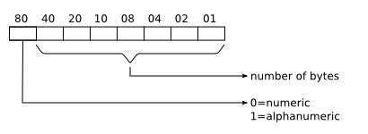
The MSB of the SOV indicates if the following bytes are an alphanumeric string (msb one) or a numeric value (msb zero). Bits 6:0 hold a binary number of the number of bytes used to hold the value. If the value is numeric, this field is always 8. If value is a string, it ranges from 1 to 124 for Wang BASIC-2, and 1 to 64 for Wang Basic.
Getting back to the description of the data record, the first value is the floating point number 1.0, followed by the floating point number #PI, followed by the 15 byte ASCII string "Wang 2200 Rocks". After the final variable of the logical record, the EOB marker byte, 0xFD, appears. This value is not a legal SOV value; 0xFD would otherwise imply a string of length 125, which is why the maximum length string in Wang BASIC-2 is 124 bytes, so it isn't ambiguous.
After the EOB marker byte, there may be unused bytes. This is also true of any sector, not just the last one of a logical record. This occurs because values are never split across a sector boundary.
After the last logical record there is typically a trailer record.
This has the value 0xA0 in the first byte of the sector, and the other
255 bytes are unused. This is written out when a
DATASAVE DC END is executed. Such a sector isn't always
necessary, as the control block at the end of the file also begins with
the value 0xA0.
References (link)
Here are some documents that I consulted in creating this document.
- Wang Disk Basic Reference Manual, pp. 67-68
- BASIC-2 Multiuser OS Release 2.5, page 1-11 (page 19 of the pdf)
- Wang Systems Newsletter No. 3, page 3
- Wang Systems Newsletter No. 5, pp. 3,4
- E-mail message from Mark Pickersgill, October 2006